GPS BASED ROBOT DESIGN
As one of the project of our Robot design and competition module of department of Electronic and telecommunication of our university we have to design a robot for an outdoor task as given below. This was a group project of five students. My team members were Dinuka Kavinda, Naveen Karunanayake, Tharani karunasena and Natasha Kularatna.
Our Robot
 | |
| front view, sonar sensors and RGB color sensor
Task as a rough plan
As the below rough sketch of the arena three robots should perform from the starting location at the same time and each of their target location will be allocated at the starting time by the examiners. So robot must have only one switch for power on and another 2 or 3 for select the target from given three. After robot start its moving it should go to the target location following GPS signals while avoiding obstacles which are placed in random placed between target and starting. In the target location, there is black partition and white partition and only the white partition contains a cylinder with 10cm high and 40cm in diameter. Inside this cylinder there is a metal ring with 6ch diameter and 6g in weight. So robot should be capable of enter to the white partition and pick up the ring using its arm from the floor of cylinder and put it back in to the starting location.
one of the Robot(This is not our Robot) is trying to pick the ring
Planning our Robot Design
Here we are using an Arduino mega board with Atmel 2560 microcontroller as the main controller unit because of we need higher number of inputs and outputs for the whole mechanism. Also, we need two serial ports for communicate with the peripherals.
Since its an outdoor event and we need a cheep and easier but efficient method the most suitable wheel type would be 4 wheel. Since the arena has a rough surface by using four wheel drive system we can get a high power. The breaking distance of the robot will be short.
Here we are using a geared DC motor magnetic with wheel encoders. However, we did not use encoders although we thought to use them for turning.
• RPM – 300RPM
• Torque – 3.6Kgcm at 2.7A
• Op voltage – 6V
• Encoder resolution – 11 x Ratio 20.4 = 224.4PPR
Motors we used for our robor
As the motor driver we used LM 298D dual H bridge motor driver based motor controller for two motors. Because the maximum current we can draw from the driver is limited only for 3A , we had to use two separated motor drivers parallel.
Navigating Mechanism
GPS
Since we were given the coordinates of the target location , we add a GPS module to the Locating system. By using GPS raw data we got the longitude and latitude of the current position of the robot. Using these data, we could create a straight path between the current location and the target location and drive robot by changing PWM values and directions of each motor.
Specifications of the GPS module.
Ø Model – UBLOX M8N neo
Ø Navigations update rate – Up to 10Hz
Ø 25x25x4mm ceramic patch antenna.
check about the module through the manufacturer's site given here.https://www.u-blox.com/en/product/neo-m8-series
Here are some example arduino codes which I used for our project.
Finding the heading
We used the HMC 5983 3-Axis digital compass module to calculate the current heading of the robot. We used the HMC 5983-3axis digital compass module for the finding current heading of the robot and for turning robot by 90 degrees or 180 degrees. It is a magnetic type digital compass which has I2C/SPI interface.
This module works as a three axix magnetometer and using the magnetic field intencity values we can calculate the heding of the module from the north.
Here are some example arduino codes which I used for our project.
For the navigating process, we used both GPS and Compass modules as a combined system. Reading from compass gives the current heading from north and the GPS coordinated can be used to calculate the heading to the target from the north.( The angle robot should turn to directly see the target)
Obstacle avoiding
First of all we made our robot for navigate without GPS while avoiding obstacles using five HC-SR04 ultrasonic range sensors. (Sonar)
For that we wrote a simple code with three front sensors For basic obstacle avoidance code.
Here is that code,
Line detection and Color detection
After we reach near the target location we had to switch our GPS signal receiving mode to Cylinder detection with white color. For this we have to come in to the white circle marked are on the floor using an IR line hunter sensors.
Line hunter sensor with IR tranceiver
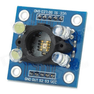
Detection of white color cylinder was done using a RGB color sensor TCS 3200.
TCS 3200 sensor
|


