Tuesday, December 19, 2017

Introduction to PLDs

Programmable Logic devices(PLDs)

A PLD is an electronic component used to build reconfigurable digital circuits. Unlike a traditional logic gate, which has a fixed function, a PLD has an undefined function at the time of manufacture which can be defined according to the end user’s requirement. Before the PLD can be used in a circuit it must be programmed, that is, reconfigured.

How PLDs realized their Programmability

A PLD is a combination of a reconfigurable logic array and a memory device. The memory is used to store the inputs that was given to the chip during programming and outputs. Most of the methods for storing data in an integrated circuit have been adapted for use in PLDs. These include:
·         Silicon antifuses
·         SRAM
·         EPROM or EEPROM cells
·         Flash memory
·         Silicon antifuses are connections that are made by applying a voltage across a modified area of silicon inside the chip. They are called antifuses because they act in the opposite way to normal fuses, which begin life as connections until they are broken by an electric current.
Antifuse

·         SRAM, or static RAM, is a volatile type of memory, meaning that its contents are lost each time the power is switched off. SRAM-based PLDs therefore have to be programmed every time the circuit is switched on. This is usually done automatically by another part of the circuit.
·         An EPROM cell is a MOS (metal-oxide-semiconductortransistor that can be switched on by trapping an electric charge permanently on its gate electrode. This is done by a PAL programmer. The charge remains for many years and can only be removed by exposing the chip to strong ultraviolet light in a device called an EPROM eraser.
·         Flash memory is non-volatile, retaining its contents even when the power is switched off. It can be erased and reprogrammed as required. This makes it useful for PLD memory.

 There are several kinds of PLDs available with different kind performances.

Simple Programmable Logic Devices (SPLDs)

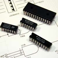
Simple programmable logic devices (SPLD) are the simplest, smallest and least-expensive forms of programmable logic devices. SPLDs can be used in boards to efficiently replace standard logic components (AND, OR, and NOT gates), such as 7400-series TTL.
They typically contain 4 to 22 fully connected macrocells which are typically consist of some combinatorial logic and a flip-flop. In other words, a small Boolean logic equation can be built within each macrocell. This equation will combine the state of some number of binary inputs into a binary output and, if necessary, store that output in the flip-flop until the next clock edge. Of course, the particulars of the available logic gates and flip-flops are specific to each manufacturer and product family. But the general idea is always the same.
Some SPLD types as follows.
SPLD Type
Details
Image
1.    PROM
(Programmable ROM)
PROM is the oldest ancestor of the PLD family which is used to create arbitrary combinational logic functions of a number of inputs. M input address and N output data line ROM can produce N separate logic circuits (of up to M inputs)
2.    PLA
      (programmable       Logic Array)
A programmable logic array (PLA) has a programmable AND gate array, which links to a programmable OR gate array, which can then be conditionally complemented to produce an output.

3.    PAL
(Programmable Array Logic)
PAL devices have arrays of transistor cells arranged in a "fixed-OR, programmable-AND" plane used to implement "sum-of-products" binary logic equations for each of the outputs in terms of the inputs and either synchronous or asynchronous feedback from the outputs.
4.    GAL
(Generic Array Logic)
This device has the same logical properties as the PAL but can be erased and reprogrammed.  The GAL is very useful in the prototyping stage of a design, when any bugs in the logic can be corrected by reprogramming. GALs are programmed and reprogrammed using a PAL programmer, or by using the in-circuit programming technique on supporting chips.


Complex programmable logic Devices (CPLD)

PALs PLAs and GALs are available only in small sizes, equivalent to a few hundred logic gates. For bigger logic circuits, complex programmable Logic Devices can be used. These contain the equivalent of several PALs linked by programmable interconnections, all in one integrated circuit. CPLDs can replace thousands, or even hundreds of thousands, of logic gates.
Some CPLDs are programmed using a PAL programmer, but this method becomes inconvenient for devices with hundreds of pins. A second method of programming is to solder the device to its printed circuit board, then feed it with a serial data stream from a computer. The CPLD contains a circuit that decodes the data stream and configures the CPLD to perform its specified logic function. Some manufacturers such as ALTERA use JTAG to program CPLD's in-circuit from .JAM files.

Field Programmable Gate Array ( FPGA)


FPGA is an abbreviation for “Field Programmable Gate Array”. Basically FPGA is a huge array of gates which can be programmed and reconfigured any time anywhere using kind of hardware implementation languages called Hardware Description Languages (HDL). “Huge array of gates” is an oversimplified description of FPGA. This is one of  advanced members of Programming Logic Devices (PLD) family. 
Altera Cyclone IV FPGA chip


In the above PLDs we were able program only the gate array for particular application. But when we are involved in complex analysis and processing through more complex logic levels we may need the programmability of the gates as well as connections. FPGA which are capable of giving the programmability to the connections is the best solution for such kind of applications.

In the next post we will discuss about further details, advantages and some cool applications of FPGA devices.

Sunday, August 27, 2017

Fundamentals of Bluetooth Low Energy

                 Fundamentals of Bluetooth Low Energy

Bluetooth is a wireless technology for communication which has simple characteristics but can give higher level of security. It is widely used in many applications belongs to vast range of fields due to low power consumption and low cost. Any two Bluetooth enabled devises which are close to each other can be connected by pairing and that creates full duplex communication for data and voice. This paring and data sharing can be done up through eight devices. One device which is called as the master device acts as a hub and other devices within the network communicate though the master device. Full duplex competences of Bluetooth help for so many smart applications by giving mobility. Bluetooth Low Energy(BLE) is initially Designed by Nokia as a part of version 4.0 specially for low cost and power consumption.


So, I think past problems which we have experienced with Bluetooth technology such as fast battery draining and regular connection losses have been overcome with BLE enabling widely usage for mobile platforms. Because of the world is becoming a global village, need of more and more smart devices to connect with each other. This technology has offered a good opportunity to peripheral vendors for improve their innovative ideas.


Bluetooth technology is very familiar with the telecommunication subjects which we are still studying and wish to study in future semesters. As we knew the fundamentals of Bluetooth technology we can expand our practical side as well as to use this BLE for embedded systems.  

Bluetooth Low Energy for Internet of Things

In the field of designing and developing Internet of things (IoT), Bluetooth Low Energy has so many benefits dues to its low power consumption wireless connectivity method.  This wireless protocol version which is available with the Bluetooth 4.0, is specially designed for low power applications such as mobile devices with small batteries, by dropping the transmitting power and data rates compared to the current 4.2 version. It has a limited power with a 50m range and data speed of 0.27 Mbps.
BLE module for Raspberry Pi

When these technology is used in a IoT applications, designers must consider the expected range and data rates and design device using strategies to attain the low energy consumption. They can also choose to have their BLE devices at all times pair with a master to launch bidirectional communications, or run in "Advertising Mode" which allows periodically send data to a receiver without using the energy desired to establish and maintain a full, two-way link for transmission of small amount of data packets.

Because of the very compact design of BLE transceiver modules it allows us to use them in most of the mobile devices related to wireless radio frequency communication. Frequent problems with Bluetooth technology such as fast battery draining and systematic connection losses have been overcome with BLE enabling widely usage for mobile platforms. This technology has offered lots of chances to inventors to get the expected functionalities of their IoT device designs. 

These are reviews for the IEEE embedded magazine articles;
http://www.embedded.com/design/connectivity/4458047/BLE-modules-simplify-IoT-design


http://www.embedded.com/design/connectivity/4442870/Bluetooth-low energy--BLE--fundamentals 

Saturday, August 19, 2017

Accident Alerting System Using SIM 808 shield

Accident Alerting System Using GSM shield


This was a kind of basic project I have involved with one of my friend who was studying at a engineering education Institute. The target was an accident alerting system for a vehicle. 

When the car getting closer to a vehicle alerting system gives a beep pulse sound to alert the driver. The driver can manually silent the alarm by separated push button switch. If the vehicle gets very closer (7cm as an example) system gives an emergency alarm to indicate an accident. The driver still can silence the alarm and ignore the incidence as a mistake by pressing the same button mentioned above within a minute. 

Unless the driver presses the button within a minute system to consider this as an accident and sends SMS to the family and police with the GPS coordinates of the vehicle, time and information of the accident. Then it automatically makes a missed call to the family as the SMS do not give an urgent alert. however as my thoughts this method has a tedious part with sing an ultra sonic sensor. 


Using SIM 808 GPRS, GSM, GPS  Arduino shield

SIM 808 module
SIM808 module is a GSM/GPS/BT three-in-one function module. It is based on the latest GSM/GPS/BT module SIM808 from 'SIMCOM', supports GSM/GPRS Quad-Band network and combines GPS technology for satellite navigation.It has high GPS receiver sensitivity with 22 tracking and 66 acquisition receiver channels. Besides, it supports A-GPS that available for indoor localization, and it also supports for Bluetooth 4.0.
The module is controlled by AT command via UART and supports 3.3V and 5V logical level.

As the above picture, there are two separated antennas for GSM and GPS. The bigger one is for the GPS and the other one is a GSM antenna. 
We must plug both of them as our application to the dedicated slot labeled on the shield. Some of the major parts of the shield can be understood using the image shown below. But it is another model of shield made by using the same SIM808 module.


Turn on the SIM808  shield

There are two ways to turn on the SIM808 GPRS/GSM+GPS Shield.

1. Turn on through the power button . Press the the 'POWERKEY' for few seconds until Power-on indicator(Green/red) is on.
2. Turn on through the software.To turn on through software run the following code, the SIM808 will POWER on or POWER off after code run.
Here is the code for turn on the device,
int Powerkey = 9;
void setup() {                
  pinMode(Powerkey, OUTPUT);   // initialize the digital pin as an output.  
  power();                     //power on the sim808 or power down the sim808
}
void loop() 
{

}

void power(void)
{
  digitalWrite(Powerkey, LOW); 
  delay(1000);               // wait for 1 second
  digitalWrite(Powerkey, HIGH);
}

Communication with the microcontroller

The SIM808 GPRS/GSM+GPS Shield is used UART (serial)protocol to communicate with an Arduino. Users can use jumpers to connect (RX,TX) of the shield to either Software Serial(D8,D7) or Hardware Serial(D1,D0) of the Arduino

Automatic Power down methods of SIM 808


Apart from normal manual power down through hardware or software, there are some automated procedures for safety and other facts involved the device. They are as follows,

1.  Over-voltage or Under-voltage Power Down: 

The module software monitors VBAT voltage constantly.
           1.If the voltage ≤ 3.5V, the following URC will be reported:
UNDER-VOLTAGE WARNNING
           2.If the voltage ≥ 4.3V, the following URC will be reported:
OVER-VOLTAGE WARNNING
          3.If the voltage < 3.4V, the following URC will be reported,and the module will be automativally powered down.
UNDER-VOLTAGE POWER DOWN
          4.If the voltage > 4.4V, the following URC will be reported,and the module will be automativally powered down.
OVER-VOLTAGE POWER DOWN

2. Over-temperature or Under-temperature Power Down
This will constantly monitor the temperature of the module.
①If the temperature > +80℃, the following URC will be reported:
+CMTE:1
②If the temperature < -30℃, the following URC will be reported:
+CMTE:-1
③If the temperature > +85℃, the following URC will be reported,and the module will be automativally powered down.
+CMTE:2
④If the temperature < -40℃, the following URC will be reported,and the module will be automativally powered down.
+CMTE:-2

Lets' Communicate with The device

Sim 808 is supported with AT commands for communication process with the user. We should send At commands as our purpose to execute it. Here are some important AT commands I found from Elecrow.com.

Back to the project

Here I used a ultrasonic range sensor for detect the distance to the closest vehicle t our vehicle from front side. When the distance is getting lower than predefined alerting limit there is a buzzer for give an alarm. Unless driver bush a separated button for this on the dashboard , alarm sounds as long as distance is low. If the distance reduce to lower than 10cm for two minutes without a button press during this 2 minutes system recognize this as an accident and send a SMS to the predefined phone number .

Here is the Arduino code for send the sms

#include <SoftwareSerial.h>

SoftwareSerial mySerial(7, 8);

void setup()
{
mySerial.begin(9600); 
mySerial.print("\r");
delay(1000);                    //Wait for a second while the modem sends an "OK"
mySerial.print("AT+CMGF=1\r");    //Because we want to send the SMS in text mode
delay(1000);


mySerial.print("AT+CMGS=\"+94123456789\"\r");    //Start accepting the text for the message
//to be sent to the number specified.
//Replace this number with the target mobile number.
delay(1000);
mySerial.print("Hello,World!\r");   //The text for the message
delay(1000);
mySerial.write(0x1A);  //Equivalent to sending Ctrl+Z 
}

void loop()
{
//We just want to send the SMS only once, so there is nothing in this loop.
I used internal GPS feature to get GPS coordinates of the vehicle.

Here is the Arduino code for using GPS

This code for Get the string which is sent from sim808 and decode it to parts as we can separate Latitude, Longitude,Altitude, date, time ,no. of satellites and so on. 
/*
Edited by Chandula N.
   st1,st2,date&time,longitude,latitude,altitude,

*/
#include <SoftwareSerial.h>
#define DEBUG true
SoftwareSerial mySerial(7, 8);
int Powerkey = 9;
void setup() {
  Serial.begin(9600);
  mySerial.begin(9600);
  pinMode(Powerkey, OUTPUT);   // initialize the digital pin as an output.
  power();
  getgps();
}

void loop() {
  sendData( "AT+CGNSINF", 1000, DEBUG);
}

void getgps(void) {
  sendData( "AT+CGNSPWR=1", 1000, DEBUG);
  sendData( "AT+CGPSINF=0", 1000, DEBUG);
}

void sendData(String command, const int timeout, boolean debug) {
  String response = "";
  mySerial.println(command);
  delay(5);
  if (debug) {
    long int time = millis();
    while ( (time + timeout) > millis()) {
      while (mySerial.available()) {
        response += char(mySerial.read());
      }
    }

    // Serial.print(response);
    int _1commaIndex = response.indexOf(',');
    int _2commaIndex = response.indexOf(',', _1commaIndex + 1);
    int _3commaIndex = response.indexOf(',', _2commaIndex + 1);
    int _4commaIndex = response.indexOf(',', _3commaIndex + 1);
    int _5commaIndex = response.indexOf(',', _4commaIndex + 1);
    String Lat = response.substring(_3commaIndex + 1, _4commaIndex);
    String Long = response.substring(_4commaIndex + 1, _5commaIndex);
    String Date = response.substring(_2commaIndex + 1, _2commaIndex + 9);
    String Time = response.substring(_2commaIndex + 9 , _3commaIndex );
    Date = Date.substring(0, 4) + "/" + Date.substring(4, 6) + "/" + Date.substring(6, 8);
    Time = (Time.substring(0, 2)) + "." + Time.substring(2, 4) + "." + Time.substring(4, 6);

    Serial.print("Lat:");
    Serial.println(Lat);
    Serial.print("Long:");
    Serial.println(Long);
    Serial.print("Date:");
    Serial.println(Date);
    Serial.print("Time:");
    Serial.println(Time);
    Serial.println();
  }
}
void power(void)            //Turn on thr sim808 
{
  digitalWrite(Powerkey, HIGH); 
  delay(1000);               // wait for 1 second
  digitalWrite(Powerkey, LOW);
}

After separation of GPS date I used sms sending code and wrote a combination for send the GPS data to a specified phone number.
You can download the combined code for sending GPS data to a specified number, which I used for this project. 


After the sms is sent , for the further alerting sysm makes a call to predefined number for a given time. This may be work as a missed call for the receiving party. 

Here is the code for making a call with sim 808

#include <SoftwareSerial.h>
SoftwareSerial mySerial(7, 8);
void setup()
{
mySerial.begin(19200);               // the GPRS baud rate   
Serial.begin(19200);               // the GPRS baud rate   
delay(2000);
mySerial.println("ATD+94xxxxxxxxx;"); // xxxxxxxxx is the number you want to dial.  

if(mySerial.available())

Serial.print((unsigned char)mySerial.read());


delay(10000); 
delay(10000); 

mySerial.println("ATH"); //End the call.
if(mySerial.available())

Serial.print((unsigned char)mySerial.read());
}


void loop()
{
//Do nothing
}

Here is my final code which I used for this project with all the functions


references-https://www.elecrow.com/wiki/index.php?title=SIM808_GPRS/GSM%2BGPS_Shield_v1.1

Tuesday, August 1, 2017

GPS Based Robot Design

GPS BASED ROBOT DESIGN

As one of the project of our Robot design and competition module of department of Electronic and telecommunication of our university we have  to design a robot for an outdoor task as given below. This was a group project of five students. My team members were Dinuka Kavinda, Naveen Karunanayake, Tharani karunasena and  Natasha Kularatna.

Our Robot

front view, sonar sensors and RGB color sensor
Task as a rough plan


As the below rough sketch of the arena three robots should perform from the starting location at the same time and each of their target location will be allocated at the starting time by the examiners. So robot must have only one switch for power on and another 2 or 3 for select the target from given three. After robot start its moving it should go to the target location following GPS signals while avoiding obstacles which are placed in random placed between target and starting. In the target location, there is black partition and white partition and only the white partition contains a cylinder with 10cm high and 40cm in diameter. Inside this cylinder there is a metal ring with 6ch diameter and 6g in weight. So robot should be capable of enter to the white partition and pick up the ring using its arm from the floor of cylinder and put it back in to the starting location.


One target location out of given three
\
one of the Robot(This is not our Robot) is trying to pick the ring 

Planning our Robot Design
Here we are using an Arduino mega board with Atmel 2560 microcontroller as the main controller unit because of we need higher number of inputs and outputs for the whole mechanism. Also, we need two serial ports for communicate with the peripherals.  

Since its an outdoor event and we need a cheep and easier but efficient method the most suitable wheel type would be 4 wheel. Since the arena has a rough surface by using four wheel drive system we can get a high power. The breaking distance of the robot will be short.
Here we are using a geared DC motor magnetic with wheel encoders. However, we did not use encoders although we thought to use them for turning.
      RPM – 300RPM
      Torque – 3.6Kgcm at 2.7A
      Op voltage – 6V
      Encoder resolution – 11 x Ratio 20.4 = 224.4PPR
Motors we used for our robor

As the motor driver we used LM 298D dual H bridge motor driver based motor controller for two motors. Because the maximum current we can draw from the driver is limited only for 3A , we had to use two separated motor drivers parallel.


Navigating Mechanism

GPS

Since we were given the coordinates of the target location , we add a GPS module to the Locating system. By using GPS raw data we got the longitude and latitude of the current position of the robot. Using these data, we could create a straight path between the current location and the target location and drive robot by changing PWM values and directions of each motor.
Specifications of the GPS module.
Ø  Model – UBLOX M8N neo
Ø  Navigations update rate – Up to 10Hz 
Ø  25x25x4mm ceramic patch antenna. 
check about the module through the manufacturer's site given here.https://www.u-blox.com/en/product/neo-m8-series
Here are some example arduino codes which I used for our project.

Finding the heading

We used the HMC 5983 3-Axis digital compass module  to calculate the current heading of the robot. We used the HMC 5983-3axis digital compass module for the finding current heading of the robot and for turning robot by 90 degrees or 180 degrees. It is a magnetic type digital compass which has I2C/SPI interface. 

This module works as a three axix magnetometer and using the magnetic field intencity values we can calculate the heding of the module from the north.
Here are some example arduino codes which I used for our project.

For the navigating process, we used both GPS and Compass modules as a combined system. Reading from compass gives the current heading from north and the GPS coordinated can be used to calculate the heading to the target from the north.( The angle robot should turn to directly see the target)

Obstacle avoiding 

First of all we made our robot for navigate without GPS while avoiding obstacles using five HC-SR04 ultrasonic range sensors. (Sonar)

For that we wrote a simple code with three front sensors For basic obstacle avoidance code.
Here is that code,

Line detection and Color detection 

After we reach near the target location we had to switch our GPS signal receiving mode to Cylinder detection with white color. For this we have to come in to the white circle marked are on the floor using an IR line hunter sensors. 
Line hunter sensor with IR tranceiver
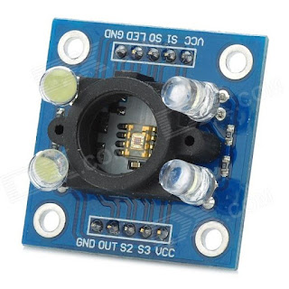
    Detection of white color cylinder was done using a RGB color sensor TCS 3200.
TCS 3200 sensor


The Featured Post

A Deep Dive into Deep Packet Inspection

This blog post aims to unfold the details of DPI, exploring its definition, methods, applications, modern technologies, and the challenges i...